|
Tech
Note 016:
Submitted
by Bill Lakow
Customer
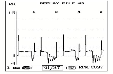
complains of a loss of power and bucking and surging. You connect your
scope and test the ignition system and discover four extra firing
events during a snap acceleration and you also notice that the firing
voltages are low (see Figure 1 below). The ignition wires, plugs and a
distributor cap appear to be recently installed. What could cause this
problem?
 A A
The
PDA provides the means to test the secondary ignition and the crank
reference signal at the same time. This test allows us to view the
relationship of the crank signal to the secondary ignition. To perform
this test, select ENGINE TEST
from the MAIN MENU and then
select SCOPE CHANNEL.
Connect a lab scope lead to the crank reference signal (see Figure 2
below).
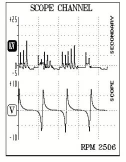
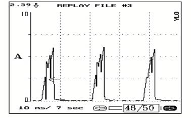
The
secondary pattern in figure 2 has more glitches during this test, but
the crank sensor signal appears to be good. The glitches in the
ignition are probably not caused by the crank sensor or the
distributor.
The
next test shows the relationship between the crank sensor and the
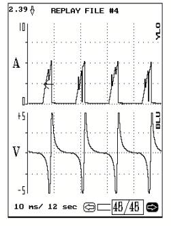
ignition module. Figure 3 (below) shows the ignition coil current on the top
and the crank sensor on the bottom. The problem is revealed in the
current waveform of the igniter. The igniter is failing to maintain
the dwell period and each time the ground fails to hold the dwell, the
field collapses and a premature firing event occurs.
Figure
4 (below) shows a more detailed look at the coil current flow. Each
downward sloping line indicates a break in the continuity of the
current flow, an open circuit. Every time the circuit opens the
primary field collapses prematurely.
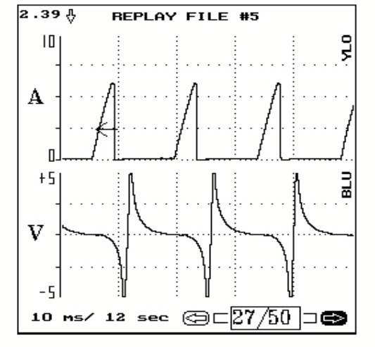
The
defective ignition module was replaced and figure 5 (below) shows a
good coil current trace over a good crank reference signal. Notice
that the current ramps, the angles of the signals, are uniform in
shape and show no dropouts in the signal.
The Milliamp Current Probe helped to quickly and accurately
diagnose this problem.
|