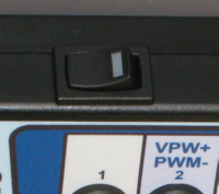
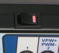
The LineSpi has two operational modes: Activity Mode and Diagnostic Mode. The operational modes allow the circuit of the LineSpi to be engaged or disengaged. When the circuitry is engaged the yellow LEDs will flash when changes take place on the corresponding data line. The flashing LEDs will allow you to determine the activity on that line. When the circuit is disengaged the circuitry for the yellow LEDs becomes fully transparent to your testing. The yellow LEDs will no longer flash.
Activity Mode - Smart breakout box
|
|
|||||||
Diagnostic Mode - Basic breakout box
|
|
When to use Diagnostic Mode
The circuitry for the yellow LED is very high impedance. In most situations this will be completely transparent to your testing and will not affect any signals on the data lines. The yellow LED circuitry can be an issue when are diagnosing a open wire to the DLC on pin 2, 10, 6, 14, or 7. For example, if you want to use a logic probe to detect an open wire you would expect these results:
| • | Wire Low = green light |
| • | Wire High = red light |
| • | Wire Signal Toggling = red or green and flashing yellow |
| • | Wire Open = no lights |
If the circuitry to LineSpi yellow LEDs is engaged (Activity Mode) then you will never be able to get a Wire Open = no lights result because the logic probe will be responding to the LineSpi circuitry. Switching the LineSpi to Diagnostic Mode and you will be able to get a Wire Open = no lights.
Other times when you might want to use Diagnostic Mode:
If you have a no-communication problem with your scan tool and you simply want to eliminate the the yellow LED circuitry.
Note: The green and red LEDs corresponding to DLC pins 4, 5 and 16 are always active.

