Ford Explorer 2002
Test point:
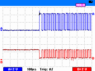
LineSpi Pin 2 = Channel A
LineSpi Pin 10 = Channel B
This waveform was captured by setting the trigger at the highest voltage of the signal on channel A (pin2 - PWM-).
|
|
|
If your scope has a recording feature the trigger point is not so critical. If your scope does not have a recording feature you may wish to hit the HOLD button to freeze the waveform.
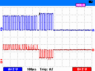
Examination of this view of the signal reveals other triggering options. Try setting the trigger as follows:
Trigger setup 1 Trigger Source: Channel B (pin 10) Trigger Slope: Rising Trigger Level: Greater than 3.5 and less than 4 volts.
Result: The scope will trigger at the beginning of the channel A shorter pulse.
Trigger setup 2 Trigger Source: Channel B (pin 10) Trigger Slope: Rising Trigger Level: Less than 3.5 and greater than .5 volts.
Result: The scope will trigger at the beginning of the channel A taller pulse.
|
|
|
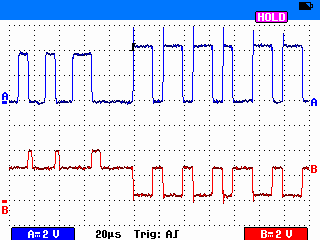
A fast 20uS timer per division setting is needed for detailed examination of the pulses. Note the various pulse widths.
|
|


